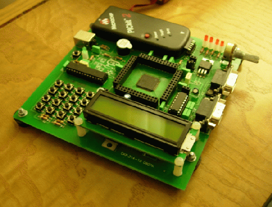
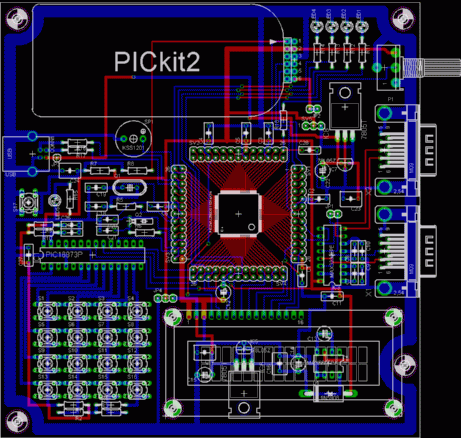
The PIC24 Experiment Board was designed to be used for the EL308
Microcomputer Based System Design course. Board features include:
- PIC24FJ256GB110 Microcontroller
- 4x4 keypad (with PIC16F57 based scan controller)
- 16x2 character LCD (with 3.3 to 5 Volts converter)
- 2x RS232 ports with MAX3232 level converters
- 4x LEDs for convenient program status display
- One buzzer
- Crystal connections for the PIC24 primary and secondary oscillators
- One linear potentiometer for 0-3.3 Volts analog input
- One USB Type B connector for direct host-microcontroller links
- Can be powered up either by a PICkit 2 or a USB Type B plug
- Pin headers to access all 100 microcontroller pins
The board interfaces to a host PC via a PICkit 2 debugger and
is supported by the MPLAB IDE. The complete board can be powered by
PICkit 2. As the debugger sets the DC level to 3.3 Volt due to the
device family, an onboard voltage doubler and 5 Volt DC regulator is
added to provide power to the LCD. Power provided by the USB port of a
computer can also be used to run the board. For this option, the board
contains a 3.3 Volt regulator for the microcontroller supply.
|
 |

