

In this step, we will enter the necessary parameters for the voltage source components.
1. Edit the properties of the DC-voltage source.
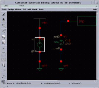
Select the DC-voltage source by clicking on it. The selected component is highlighted by a bright box (rectangle) around it.
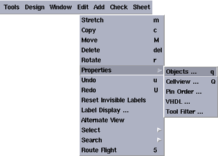
Click Edit on the menu bar and select Properties and Object, respectively.
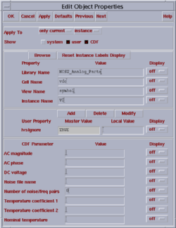
The Edit Object Properties window appears.
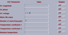
Edit the DC voltage field in the Edit Object Properties window and type the VDD value which is 3.3V in our examples.
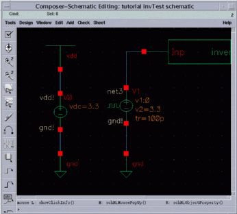
Click the "OK" button on the Edit Object Properties window. You can observe the new value entered for the DC-voltage near the DC-voltage source.
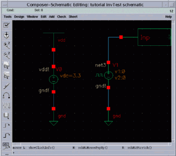
2. Edit the properties of the pulse generator
Select the pulse generator instance in the schematic.
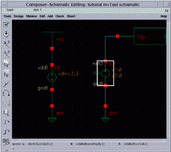
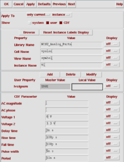
The Edit Object Properties window for the pulse generator appears.
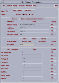
The parameters which are listed in the image above are used to define a pulse which will be repeated periodically. How to use these parameters to define the input pulse waveform is explained in the figure below.
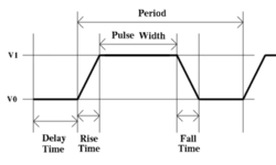
The following image shows the values for the pulse generator parameters which are used to define the input waveform. Click on OK to apply these changes and close the Edit Object Properties window.
Finally, the new values for the important parameters of the pulse generator appear near the its instance.
a production of


Cadence is a trademark of Cadence Design Systems, Inc., 555 River Oaks Parkway, San Jose, CA 95134.
Please read this DISCLAIMER