
1. Click on Analyses in the menu banner and select Choose.

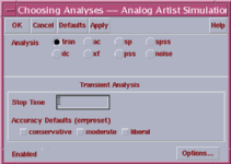
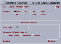
The Choosing Analyses window appears where you can choose the simulation type.

2. Click on tran in the Analysis field.
There are many available analysis options you can choose. Each of these options provides a specific sub-region within the Choosing Analysis window. Since we want to obtain the delay information for the inverter, we choose the transient simulation type, so that the output can be traced in time domain.

In the Transient Analysis region, type a value in the Stop Time field to determine how long the simulation will take place. The Stop Time is chosen 30ns (nanoseconds).
Note :
Do not leave any space between the numeric value and the unit. Do not type "s"
after the unit where "s" stands for "seconds".
Do not forget to type a
unit after the numeric value, otherwise, the stop time for the simulation
will be something in seconds which means your simulation will last forever !
3. Click on OK in the Choosing Analyses window to close it and to go back to the Analog Artist window.
a production of


Cadence is a trademark of Cadence Design Systems, Inc., 555 River Oaks Parkway, San Jose, CA 95134.
Please read this DISCLAIMER