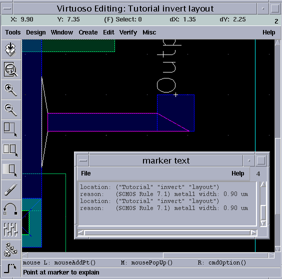
Design Rule Check (DRC)
Please follow this example link for a description of how to run DRC on a layout.

Please follow this example link for a description of how to run DRC on a layout.
The created mask layout must conform to a complex set of design rules, in order to ensure a lower probability of fabrication defects. A tool built into the Layout Editor, called Design Rule Checker, is used to detect any design rule violations during and after the mask layout design. The detected errors are displayed on the layout editor window as error markers, and the corresponding rule is also displayed in a separate window. The designer must perform DRC (in a large design, DRC is usually performed frequently - before the entire design is completed), and make sure that all layout errors are eventually removed from the mask layout, before the final design is saved.

a production of


Cadence is a trademark of Cadence Design Systems, Inc., 555 River Oaks Parkway, San Jose, CA 95134.
Please read this DISCLAIMER