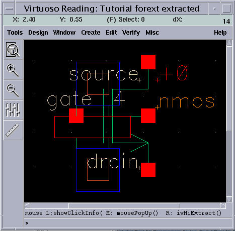
Circuit Extraction
Please follow the example link (button) for a detailed description of "Circuit Extraction".

Please follow the example link (button) for a detailed description of "Circuit Extraction".
Circuit extraction is performed after the mask layout design is completed, in order to create a detailed net-list (or circuit description) for the simulation tool. The circuit extractor is capable of identifying the individual transistors and their interconnections (on various layers), as well as the parasitic resistances and capacitances that are inevitably present between these layers. Thus, the "extracted net-list" can provide a very accurate estimation of the actual device dimensions and device parasitics that ultimately determine the circuit performance. The extracted net-list file and parameters are subsequently used in Layout-versus-Schematic comparison and in detailed transistor-level simulations (post-layout simulation).

a production of


Cadence is a trademark of Cadence Design Systems, Inc., 555 River Oaks Parkway, San Jose, CA 95134.
Please read this DISCLAIMER