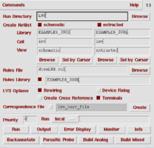

In this step we are going to compare the schematic and the extracted layout to see if they are identical.
1. From the Verify menu select the option LVS.

If you had previously run a LVS check, this would pop-up a small warning box. Make sure that the option Form Contents is selected in this box.

The top half of the LVS options window is split into two parts. The part on the left corresponds to the schematic cell view and the right part corresponds to the extracted cell view that are to be compared. Make sure that the entries in these boxes represent the values for your circuit.
Although there are a number of options for LVS, the default options will be enough for basic operations, select Run to start the comparison.

The comparison algorithm will run in the background, the result of the LVS run will be displayed in a message box. Be patient, even for a very small design the LVS run can take some time (minutes).

The succeeded message in the above message box, indicates that the LVS program has finished comparing the netlists, NOT THAT THE CIRCUITS MATCH. It might be the case that the LVS was successful in comparing the netlists and came up with the result that both circuits were different.
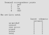
To see the actual result of an LVS run you have to examine the output of the LVS run. The Output option is right next to the Run command

You can take a look at the complete LVS result here. The most important part of the report can be found in the figure above. It states that the netlists did indeed match. If you discover that there is a mismatch, you must go back to the layout view and correct the error(s).
Most of the other options on the LVS form, are for finding mismatches between two netlists and to generate netlists that include only parasitic effects relevant to one part of the circuit.
a production of


Cadence is a trademark of Cadence Design Systems, Inc., 555 River Oaks Parkway, San Jose, CA 95134.
Please read this DISCLAIMER